Monday, March 25, 2013

What is your plan?


I am a huge advocate for continuing education.  I feel you can always learn more about the job you are doing, no matter how long you have done it.  I still learn things from customers, and I love to see the ingenuity that comes out of equipment manager’s shops. 

Unfortunately I don’t see many technicians with a formal learning plan.  When I hire a technician in my shop I set them up on a plan with specific goals.  I want them to strengthen their technical skills, and feel good about what they are doing. 

One big opportunity for technicians in our field is the certificate program with the International Golf Course Equipment Managers Association.  IGCEMA has a wonderful program that covers 6 specific areas.  They have study materials and opportunities for online testing that make it easy to learn.

Hydraulic Troubleshooting
Electrical Troubleshooting
Internal Combustion Engines
Drivelines
Sprayer Troubleshooting
Cutting Units

I highly recommend this program to anyone working on turf equipment.  Set up a timeline to complete the 6 tests to help push you when other things may get in the way.   I am confident enough in this testing process that I require my technicians to complete these same tests.

Of course there are other options as well.  I know Toro (as well as other manufactures) puts on service classes to help train technicians, and there are also opportunities at many of your local distributors.  I put on classes in both ND and MN this past year for our customers at MTI.  Other options may be your local technical college.  Is there a welding or engine class you could learn from?

Whatever you choose, I suggest you make a thoughtful plan and write it down.  Put a realistic timeline to it and push yourself to complete it.  If you want help putting together a plan like this reach out to me via email – jim.king@mtidistributing.com or Twitter - @TOROKING  and I will be happy to help you reach your goals.  My true goal for this blog is to help others who want to learn and better themselves.

Plan your work, and work your plan.

Thursday, February 21, 2013

What is Clip?


If you have any reel mowers it is important to understand what clip is.  When we talk about cutting units, the term clip is used to explain the distance between cut marks in the turf.


To fully understand clip, you need to understand basic cutting unit theory.  A reel will gather grass before it cuts it.  At a magnified level you will see waves in the grass after any reel has cut it.  The distance between the bottoms of these waves is your clip.  This is why crosscutting still produces clippings, and makes for a smoother surface.


There are several factors that determine clip.  The number of blades on the cutting unit, the speed of the reel, and the speed of the machine.  It is important to match your clip to your height of cut.

So how do we make sure it matches?  To start, we need to make sure we have the correct reel for the job.  Make sure you match your height of cut to the number of blades. Next use the reel speed charts to correctly set your reel and traction speed.

Reel chart on Greensmaster


Can we have a clip too small? - under certain conditions you can have a clip that is too small.  Think of trying to use a 14 blade reel to cut heavy grass at 1.5 inches.  There is just nowhere for the cut grass to go.  The other thing you can see is your clip will be so close you are introducing more stress to the turf.  I compare it to double cutting every day.  Under certain stressful situations you may not want to introduce more stress.


Clip Marks in turf

If this shows up on turf that normally looks fine.  You are typically seeing either an operator going too fast, or a reel that is not spinning fast enough.  If you can slow down and the problem goes away, then you are fine.  If you have to slow down more then normal, or slowing down is not helping, the reels are not spinning fast enough.  At this point try to adjust the reel speed faster.  If the reels don't spin faster, you are looking at a hydraulic issues. 

Reel Speed adjustment on 5010 series Mowers


The two biggest things I see contributing to this are o-rings in the reel control cartridges or reel motors worn.  It is important to remember that one worn motor can cause a series of reels to slow down.  One motor on a triplex, will slow down all three, one motor on a fairway unit will slow down either all three of the front or both of the rear.  In a future post I will cover testing reel mower wear.

Monday, January 21, 2013

What is a Bench Plate?


AccuProducts Bench Plates

Does your shop have a bench plate?  A Bench Plate is a precision ground aluminum plate that allows us to level and parallel a cutting unit.  Why is this important?  Doing this allows the rollers and the cutting edge to be on the same plain.  If they are not parallel when you make passes with the mower you will be introducing a mismatch.  If two cutting units side by side have a mismatch you can easily have a surface that will effect ball movement.  The lower you cut, the more important it is. 
   
Have you ever rolled a cutting unit on concrete and noticed it rocked?  This is the easiest way to tell if a cutting units rollers are not parallel.  Now with the newer styles of cutting units that hold their position much better you need to have a bench plate to truly tell where each unit is at.
How is it used?

***Important to remember*** 
This is assuming you have properly ground the reel first and there is no taper in the reelstock.  Grind your reels first then put them on the bench plate for the best results

With the bedknife removed you place the cutting unit on the plate.  You have the cutting edge of the reel on the raised surface and put slight pressure on the rear roller.  Try to slide a feeler gage or piece of paper under the rear roller.  If the paper fits on one side or another the roller is not parallel to the cutting edge.   If you are setting up a Toro DPA cutting unit you can loosen the side plate bolts slightly then allow the frame to settle into proper position.  For older cutting units you may have to bend the frame slightly to achieve this. 


Cutting edge on raised surface


sliding paper under roller

Side plate bolts 


Other things to keep in mind


Rear Roller Adjustment Kit-
This kit (part # 114-4630) allows you to adjust the roller on a DPA cutting unit.  Manufacturing tolerances are very tight and simply loosing the side plates is often enough.  If it is not and you are cutting at very low height of cuts.  I would suggest you install this kit on your greensmowers.  Is is an eccentric for one side of the roller and allows roller adjustment.  One kit per cutting unit is needed. 


Kickstand #119-8010-03
The Kickstand-
If you are setting up a DPA cutting unit, you should be using this make sure you do not adjust the bedknife contact while the reels are sitting on the adjustment nuts.  Failure to do this will often result in the contact amount changing once the reel is flipped back down.  

the Cutoff Bar mounting holes are slotted for adjustment
The Cutoff Bar-
This small piece of metal is adjustable based upon your conditions.  The gap between this plate and the cutting edge determine the airflow and clipping dispersion of the cutting unit.  This should be adjusted as your reels wear.  If you find your clippings are not making it into the baskets properly, adjust this bar. 

Bearings-
This is the most critical part of any reel, and I don’t think they get near enough attention. The bearings in the reel and rollers determine if we can achieve proper HOC and keep it.  If you have run out of .010 in both your front and rear roller, you could be seeing a +-.020 (not to mention the reel bearing) Try to cut a green below .120 with that much variance and you will notice very quickly.  You can easily determine bearing run out with a dial indicator, or an AccuGage.  

Monday, January 7, 2013

Picking the Brain


I want to go over how to use the Standard Control Module (SCM) to diagnose a machine.  The SCM is called many things, the brain, the computer, the box, etc, but what we need to know is that what goes on inside is not magic, but logic.  At the core of the SCM it only understands inputs (what we do) and outputs (what the machine does).


The SCM does a lot of cool things, It controls the basic functions of the machine, handles the safety interlock, replaces relays, and shows us what is going on with the machine.  The best thing about an SCM is that you do not need any special tools to do basic system checks.  That is what those lights are for.

Procore 648 SCM


While there will be different decals on different machines, there are some things that will always be the same.  First, there there are three boxes on the decal.  One box has a red LED, this is the power light.  When ever the key is on the red light should be on. No Red LED = No power check fuses, battery etc.  

Next is the big box on the opposite side of the power light. (or everything not in a box)  These lights show us the inputs, or switches that are open or closed.  (The switches on machines with an SCM all go to ground)  Some examples of these switches are, over temp, seat, neutral, PTO, and head position switches on a Procore.  The decal has a symbol to show us what switch it matches up to. 

Last is the smaller box.  This is for the outputs, what the machine does when the correct inputs are met.  Outputs are things like solenoids.  Example, when we are in neutral, in the seat, the PTO is not engaged, and we turn the key to crank, the output light for crank will light.  


7200 SCM
Above you can see what the lights look like on a 7200.  The reason there are two lights for the temp is because this machines uses a two step shutdown.  The first light comes on and the PTO will shut off, the second light will come on and shut down the machine.  

I think the most useful situation for using the lights is in a “no start” situation.  You can easily check the safety interlock, and see if the SCM is sending the correct outputs.  


The most common machines to use the SCM are the 7200, 3500, Procore, 4500 & 4700 (years 2004-2008)


Here is where to find it-


7200 right side panel


Procore 648 SCM 

3500 SCM 


Monday, October 8, 2012

Do you need an adjustment?

Aeration season is full of planning and preparation. When it comes to your equipment, you may check the operation, order tines, etc, but have you ever read your operators manual for adjustments?


Toro Procore 648

The Toro Procore 648 is a great machine, the efficiency of this machine is incredible. Within the operators manual (page 43) is a procedure for Resetting the Ground Following System.  This adjustment is often overlooked on this machine, and does need to be adjusted from time to time.

The ground following system uses the depth handle adjustment, and the position of the turf guards to determine the depth of the coring head.  If this is not properly adjusted you may not be getting the proper depth.

How to make the adjustment-

Insert a 5/16 bolt through the hole in the turf guard holding bracket and the hole in the frame.  This holds the turf guard in the proper position.

Hole in frame for bolt

Turf Guard frame with bolt in place

Move the depth adjustment handle to the "H" position.

Depth adjustment handle 

Connect a multi-meter (set on Ohms) to the outboard ball switch. (I like to set it to beep when there is no resistance)

Connect to switch closest to rod

Loosen the jam nuts on the top and bottom joints of the adjustment rod.

Adjust the rod until the ball switch circuit closes. (zero resistance) Tighten the jam nuts and remove the 5/16 bolt.  The Ground Following System has been reset.

Jam nuts are LH & RH threads to make adjustment easier


Setting the depth manually- 


If you would like, you can set the depth of the Procore manually.  You do this by flipping the Ground Following System switch to the off position.  (This is the switch with the bolt through it)


Ground Following Switch has a bolt to keep in position
You will then set the depth with these spacers.  When you press the switch to activate the coring head it will drop to the stops on the frame.  The spacers determine the depth, just like the height of cut on many of our rotary mowers.  *When you switch back, make sure all the spacers are back on top or, maximum depth will not be achieved.

Manual depth spacers
If you are ever in the process of aerating and you do not appear to be getting consistent depth with the holes.  First adjust the Ground Following System.  If that does not address the issue, flip the switch and try it in manual.


Tuesday, September 18, 2012

In the Red Zone

No, I am not talking about Football, I am talking about machines running hot.  The red zone for operating temp is never a good thing.  I take a fair amount of questions about cooling systems running "hot" or just under the red zone.  I will try to explain how the cooling systems operate and how we check them in our shop.

First off I should state that the electrical system on Toro equipment is designed to help identify an overheat situation.  This helps us by either shutting the machine down, (or in more recently built machines) shut the PTO system off first, then if the temp continues to rise, shut the machine down.  These systems are in place to save the engine from severe damage that can occur from an overheat situation.  I caution people to never disable this function.

So what do you do if your machine is overheating?  Virtually every time I see this issue it is related to one thing.  Not enough airflow through the radiator.  Either the fan is not spinning fast enough, or the radiator is plugged.  This is how we diagnose this-

1.Check the belt tension

We test the belt tension with a 13mm wrench and put it on a fan mounting bolt. We then try to turn it clockwise.  Can you turn the pulley with minimal force?  If so, the belt is too loose causing the fan to not spin fast enough.

2. Check the radiator for airflow blockage

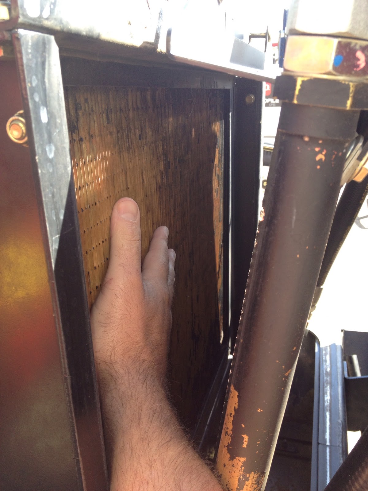
Without proper airflow over the radiator the is no chance the cooling system will operate properly.  The easiest way to tell if you are getting airflow through the radiator is to check it with your hand.  when I perform this test I open the hood, move the oil cooler out of the way and place my hand next to the radiator.  *Do this when the machine is cold to insure the radiator is not to hot to touch!  Move your hand around the radiator.  Do you feel good flow through ALL areas of the radiator?  Too often the corners or the bottom third are plugged solid.  People blow out the center and feel they cleaned it, but they have missed portions.  The other biggest problem I see is people using water to clean radiators.  This will cause the bottom of the radiator to become completely plugged.  It creates a concrete like surface that can not be blown out with air once it drys.  We often have to completely remove the radiator to properly clean it at this point.


3. Check the Fan Clutch

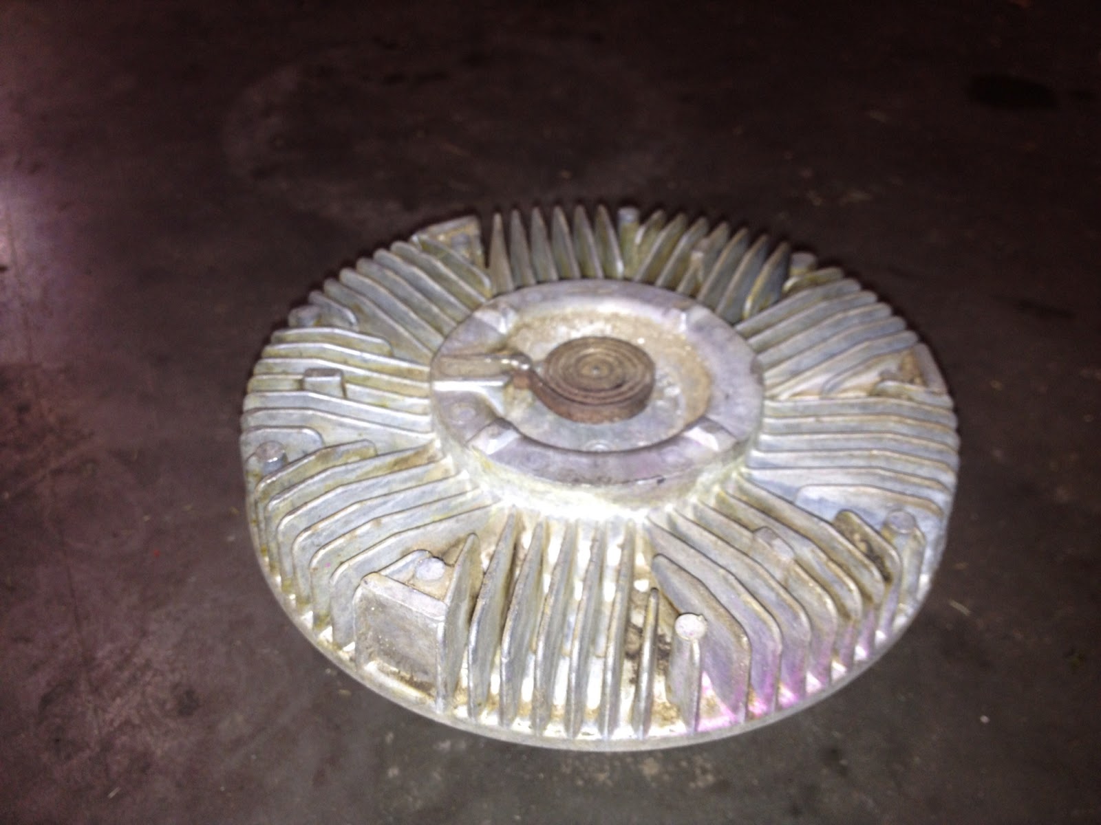
The fan clutch determines how fast the fan will spin.  This is the aluminium piece that the fan is mounted to. There is fluid inside the clutch that stiffens up when the clutch warms up.  So when the machine is cold there should be little resistance in the fan clutch.  When warm, the fan should be harder to spin. If there is no change, the fan clutch is bad, and you are not spinning the fan fast enough.


*If the spring steel coil is missing from the front of the clutch, the clutch needs to be replaced 


3.1 The Direct Drive Kit (Toro #117-5665)

If your fan clutch is bad (or you do not feel you are getting enough airflow) there is a Direct Drive fan clutch replacement kit.  This kit was designed for machines with a cab & AC that put a heavier load on the engine.  This kit is a aluminium block that removes the clutch and bolts the fan right to the pulley.  There are some downsides to this approach though.  The increased fan speed will increase machine noise. (Hearing protection is recommended) You may also need more frequent radiator cleanings and may influence the fan belt life.


Check the seal of the rear screen

Once you have determined what the root cause of your overheating problem is, another thing to watch for is how your hood seals against the radiator when it is closed.  If there is not a proper seal, grass and other debris will plug the radiator much faster.  Look at the weather stripping around the rear screen, does it make a good seal?  If you have a 4500-D or a 4700-D the rear screen swings out of the way.  Over time this screen can get bent and may need to be adjusted to get a proper seal.


Of course there can be other factors the come into play with an overheating concern, but from my experience these are the most common causes.

Jim


Wednesday, September 12, 2012

What's that black box for?


That black box that has been collecting dust on your shelf is an ACE Diagnostic Display Tool (Toro Part# 85-4750).  This (in my opinion) is the most underutilized tool in an Equipment Managers tool box.   

ACE Tool 

The ACE Tool first made its appearance in 1989 with Toro's 580-D.  Toro needed a way to troubleshoot the "brain" of the tractor. This tool allows us to test all of our input switches, the controller, the wiring, and the outputs, all in a matter of seconds without ever leaving the seat or pulling out an electrical schematic.  Sound like it may be time to blow the dust off of it yet?

Lets take a scenario in which the tractor will not crank.  The first thing I would do is find the loopback connector and plug in the ACE tool.  Now I can test the most common of issues.  Does the neutral switch work?  Move the pedal and watch the light go on and off, yep the neutral switch works.  Does the seat switch work?  Sit down and check the light, yep that one works. Turn the key to crank, and no light? You have just narrowed the issue down to the key switch or the wiring to the controller.


Loopback Connector 

This is something that can be done in the field without any other special tools, or test equipment. Of course there are times where you will need a good multimeter and a schematic, but why jump to that if there is an easier way?

Those of you familiar with the tool may have noticed I have not mentioned the overlay that is used with the ACE tool.  This is a plastic sheet that tells you what each light means when it goes off and on.  It is specific to each model number.  For the example above, I did not need the overlay.  all I was checking was inputs.  When we get a little deeper into troubleshooting, we will want to test what the controller is telling the machine to do and that is when knowing what each light means will help us.

*Do not let not having the correct overlay keep you from using the tool!

ACE Overlay

The best advice I can give someone trying to use the ACE Tool for the first time, is just plug it in and try it.  Once the lights come on, start flipping switches (inputs) and see what the tool does.  You will get the hang of it very quickly.  Press the toggle input-output button and find out what the controller is telling the machine to do.  Do you having a flashing output light? there is a fault in that circuit, check that output.

Not all of Toro's machines have the ability to use the ACE Tool.  Some of the machines that work with this are- 580-D, Reelmaster Fairway units, & Groundsmaster 4000 series units with switches to lift the decks.

*As a side note- If you have a leak detector on your fairway unit.  You need to be using this tool when you fill your machines hydraulic tank to ensure it works properly.

Some of the other units use a Standard Control Module with built in diagnostic lights.  I will cover this in an upcoming post.