You may be asked to do this by the machine, by your service department to clear a code, or for periodic maintenance. The frequency needed will be determined by the machines duty cycle. The harder you work the machine the more the DPF can burn off particulate matter during normal operation. If the duty cycle is low and the DPF is not operating at a high enough temp to burn off material, it will slowly build up and will need to be put into regeneration. This video explains how to do that.
Thursday, June 16, 2016
Stationary Regeneration on a Tier 4 Machine
Thought I would resurrect this blog to post a video on how to manually put a Tier 4 Toro unit into Stationary DPF Regeneration using the on-board InfoCenter.
Friday, May 9, 2014
What is the cost of a leak?
How old is your fleet? If it is older then 2 years old, you may want to think about replacing the moving hoses to your cutting units. Over time the constant on/off pulsing and heat that is caused from normal operation can cause wear on hydraulic lines. Not to mention friction from bending and moving against other parts of the machine.
Toro offers Cutting Unit Hydraulic Hose Kits as part of their Performance Parts Catalog. These kits allow you to order one part number and get all the critical moving hoses for your machine. I hear people tell me that it is too expensive to replace hoses as a preventive measure, and to that I ask, what is the true cost of a leak?
As a example, the kit for a Greensmaster 3150 is just under $530. What is the cost of a leak? Can you count on your operators to catch a leak quickly? What are the intangible costs? Things like negative appearance, and member reaction are hard to but dollars to. There is always the possibility that a hose might blow on the weekend. Now this adds to whole picture.
My personal opinion is replacement of moving hoses is something that should be budgeted for, and performed on a strict schedule. If a hose blows and the root cause is not abrasion, every other moving hose on that machine is now suspect. If they are showing wear, or older then 2 years, they should be replaced as a set. This is also called out in the operators manual of each unit under the service schedule.
I don’t post this to sell parts. I post this to help you keep your machines in the best possible condition, and to help you minimize downtime and turf damage. We all know hoses don’t blow on the wash pad. They blow while the unit is mowing, and quite often early in the morning when it is tough for operators to see what has happened.

Tuesday, December 10, 2013
It's all in the angle
Thought I would make a quick post about bedknife angles now that people are starting to grind their reels.
The grind on a bedknife is very important, and every bedknife should be ground. (including new ones) This ensures a parallel surface for the reel. Another thing that often gets overlooked is that bedknives should be tightened with a torque wrench to ensure they do not twist when tightened down. I have seen it where people tighten them too much and then have to take off a lot on each of the ends of the knife to get it straight. People quickly blame the bedbar when it is often the knife bolts.


The grind on a bedknife is very important, and every bedknife should be ground. (including new ones) This ensures a parallel surface for the reel. Another thing that often gets overlooked is that bedknives should be tightened with a torque wrench to ensure they do not twist when tightened down. I have seen it where people tighten them too much and then have to take off a lot on each of the ends of the knife to get it straight. People quickly blame the bedbar when it is often the knife bolts.
- Make sure the bedbar threads are clean.
- Use new Toro screws. Apply anti-seize lubricant to the screw threads before installing.
- Tighten the screws working from the center toward each end of the bedbar. DO NOT use and impact wrench.

Fairway/utility mowers:
250 - 300 in.lb.
Greensmowers:
200 - 250 in.lb
200 - 250 in.lb
Make sure you are grinding your knives to the proper angle. If the angle is off I have seen very sharp reels that won't cut paper even when tightened down. Use the guide below to make sure you have the correct angle. I have it taped to the wall next to our grinders.
Here is the bedknife angle chart that Toro has-


Thursday, September 26, 2013
Reading faults on a Reelmaster 5010
Occasionally things do go wrong, and when they do on a Toro Reelmaster 5010 series mower we have an advantage. The diagnostic light on the operators control panel allows us to determine what kind of fault the machine is having.
When there is an active fault on this unit, the red diagnostic light will begin to flash rapidly. This tells the operator something is wrong. If the fault is not happening continously the light will go out once you turn the machine off and then back on. So now we know there was a fault, what do we do?
We need to put the unit into Fault Retrieval Mode. This will let the machine tell us the last three fault codes that happened. These are stored in the machines ECM. There is no special tool that is required to do this, it is a simple list of steps.
1- Seat should be unoccupied. (make sure the switch is not jumped)
2- Machine should be in neutral, and the PTO switch is off
3- Mow/ Backlap switches need to be in Mow
4- Mow / Transport lever should be in Transport
5- Then hold the joystick in the raise position as you turn the key to run
The diagnostic light should now begin to blink codes at you if there are any codes stored.
Above you can see what it looks like when the machine has stored three codes. There is a two digit code followed by a short pause then the next, then the next. After the three there is a long pause. This is telling you it is starting over. If there is nothing stored you will see a steady one flash
Once we know the codes, we can refer to the service manual to see what they mean.

Once we have dealt with the codes we can then clear the memory so we can tell if they occur again. To clear them, do the following.
1- Place the machine in fault retrieval mode (see above)
2- Move both Mow / Backlap switches to Backlap
3- Move the joystick to the raise position
4- Diagnostic light will switch to a continuous flashing pattern
Of course operators do not always tell us when there was a flashing red light on the dash if it goes away. So if you get in the habit of checking for faults on these machines during your normal service you may find something that will help eliminate future downtime, or may point you to another issue. For example you may find that one of your units is giving a frequent overheating fault. If your operators never tell you may risk engine damage if you don't look further into it.
 |
| The top red light is the diagnostic light |
When there is an active fault on this unit, the red diagnostic light will begin to flash rapidly. This tells the operator something is wrong. If the fault is not happening continously the light will go out once you turn the machine off and then back on. So now we know there was a fault, what do we do?
We need to put the unit into Fault Retrieval Mode. This will let the machine tell us the last three fault codes that happened. These are stored in the machines ECM. There is no special tool that is required to do this, it is a simple list of steps.
1- Seat should be unoccupied. (make sure the switch is not jumped)
2- Machine should be in neutral, and the PTO switch is off
3- Mow/ Backlap switches need to be in Mow
4- Mow / Transport lever should be in Transport
5- Then hold the joystick in the raise position as you turn the key to run
The diagnostic light should now begin to blink codes at you if there are any codes stored.
Above you can see what it looks like when the machine has stored three codes. There is a two digit code followed by a short pause then the next, then the next. After the three there is a long pause. This is telling you it is starting over. If there is nothing stored you will see a steady one flash
Once we know the codes, we can refer to the service manual to see what they mean.

Once we have dealt with the codes we can then clear the memory so we can tell if they occur again. To clear them, do the following.
1- Place the machine in fault retrieval mode (see above)
2- Move both Mow / Backlap switches to Backlap
3- Move the joystick to the raise position
4- Diagnostic light will switch to a continuous flashing pattern
Of course operators do not always tell us when there was a flashing red light on the dash if it goes away. So if you get in the habit of checking for faults on these machines during your normal service you may find something that will help eliminate future downtime, or may point you to another issue. For example you may find that one of your units is giving a frequent overheating fault. If your operators never tell you may risk engine damage if you don't look further into it.
Thursday, August 22, 2013
Keeping your cool
When the weather gets hot we rely on the Air Conditioning in
our units with cabs on them to help keep us cool. These systems work great, but there is some maintenance
to them as well. When it is hot, you
blow out your radiator to keep your engine cool, but sitting on top of that cab
is a different kind of radiator that needs to be serviced to keep you cool.

It helps to understand how the AC system works to know
exactly how service affects its performance.
No matter where the AC system located, in a house, a car, or in a Toro mower, the
basics of the system are the same. There
are three main components to the system.

Compressor –
Spun by the engine and charges the system
Evaporator coil
– This is the coil that gets cold and we force air over it to cool the air in
the cab. It is located above the
headliner within the cab.
Condenser coil –
This is the coil that gets hot and we force outside air over it to cool
it. Just like a radiator for the
engine. It is located on top of the cab
and has a fan mounted on it.
You may have heard about high and low limit switches on an
AC system. The low switch turns the system
off if the pressure gets too low. (If
there is a leak) The high pressure switch shuts the system off if the pressure
gets too high. This happens when can’t cool
down the condenser coil because we cannot get enough air across the coil. (Typically
because it is plugged)
 |
| AC Compressor |
The top things I see affecting AC performance on our units
are a compressor belt not being tight enough, or a plugged condenser coil tripping the high pressure switch. A plugged coil can put stress on the entire
system causing other failures as well.
Pump seals, hose fittings, and coil leaks can all result from a plugged
condenser coil.
 |
| Pull out screen under coil |
There is a screen located beneath the coil to help keep the
coil from plugging up, but it needs to be serviced regularly. Just like the engine radiator, how often it
needs to be cleaned depends on the conditions.
If you have to blow out your radiator more often, your AC condenser will
also need to be cleaned. Just cleaning
the screen may not be enough at times.
You may have to pull the fan and shroud to gain access to the coil. With this removed, you can properly clean the
coil with compressed air and or water.

Keeping the condenser coil clean will help keep stress off
the system and keep you cool when you need it most.
Wednesday, July 3, 2013
Understanding the Traction Circuit
To fully understand how the traction system works on turf
equipment you first have to understand some basic principals-
When talking about hydraulics there are two key terms- Flow
and Pressure. Flow is the movement of
fluid (how we get speed) and Pressure is the resistance of flow (how we get
torque).
Hydraulic flow moves to the path of least resistance, just
like water, and electricity. Think of
this as an open differential on a vehicle.
If you jack one side of a vehicle up all the power goes to the wheel
with no resistance. This same reason it allows
you to take a tight turn without the tires binding. If your vehicle is in 4WD (or you lock and axle) and you make a
tight turn it is much tougher and if you are on grass you are going to tear
turf.
It is the same with turf equipment. The reason being that with independent wheel
motors when they are both on the ground and both have equal resistance you have
“all wheel drive” When you make a turn
there is more resistance on the inside wheel motor so more fluid goes to the
outer motor allowing them to spin at different speeds and makes it so you will
not scuff turf.
Now imagine you are going in a straight line through a very
wet spot. One wheel starts to spin. What happens to the fluid? It goes to the path of least resistance and
you stop. If you were to apply brake
pressure to the wheel that is spinning, (with split brakes) you would increase
the hydraulic pressure forcing the fluid to balance out. Training your operators to do this will allow
them to drive through more difficult situations.
There is also an option called a Flow Divider found on many
Toro pieces. This is a momentary switch
that you hold down while driving through a bad spot. What this does is split fluid to both the
front and rear wheel motors allowing balanced flow even if a motor starts to
spin. It does this in FORWARD only and
the way it works is that it forces fluid over a set of orifices or small
openings in the block of the same size.
Now that we have some basics down we can look at the
schematics. Here is the traction circuit
of a 4000- D You will see this same
circuit duplicated in many other machines.
 |
| Toro 4000-D Traction Circuit |
The pump is on the left. (pumps have arrows pointing out) There is an arrow through it because we can
vary the amount it puts out depending on how the traction pedal is pushed. There are arrows in two directions because we
can go in both forward and reverse. The
motors have two arrows going in because they accept fluid in both
directions.
In the drawing you can see the closed loop circuit. The solid darker lines are pressured fluid
the dashed darker lines are return fluid.
We need to run a closed loop to for several reasons, but one of them is
that it is very hard to filter fluid at 4000-5000PSI in two directions. So how do we filter and the fluid? -Charge Fluid. Charge is make up fluid that fills the back
side of the circuit refilling the circuit with cooled, filtered fluid. As you can see in the schematic both the
front and rear wheel motors leak off some fluid by design - dashed lines coming
out of motors.
The flow in the diagram shows the circuit in Mow or when we
are in 4WD. If we flip the switch to go
to High/Transport, PD1 &PD2 valves shift to block off flow to the rear motor and
all the flow goes to the front wheel motors.
This is why we go faster in high.
Remember flow is speed and we are sending more flow to the front
motors.
One last thing I want to add is a pump and a motor in hydraulics are basically the same thing. The only difference is that a pump is spun by an outside force and the motor accepts fluid. This is why if you push a machine with a closed loop circuit the motors turn into pumps and produce flow until it hits what was the pump. It now turns into a motor and has the resistance of whatever was spinning it. That is why the wheels lock up, and why there is a bypass / tow valve on these machines. When you open that up the closed loop goes to the path of least resistance and bypasses the pump allowing the fluid to spin freely through the circuit. Only problem being that we are still bleeding off some fluid and now charge flow is coming in to make up for it. This is why you should not tow the machine very far or fast or you can cause damage to the wheel motors. (you run them dry)
In a future post I will cover the 4WD manifold in more
detail.
Monday, April 29, 2013
Calibrating the Toro ProControl
This is how to set up your ProControl. Anytime I have a question with a sprayer’s
performance I start here to make sure we have all the basics set properly.
To start we need to make sure our bypass valves are completely
closed. We also need to find the flow
meter and look at the tag on it. There
should be a meter cal number on it.
 |
| Set bypass to 0 when using a ProControl |
 |
| Meter Cal # tag |
Then we move up to the controller. Hold the CE button down and power up the
controller. This will clear the
controller and allow us to set it up again.
We can now select what scale we want to use. US is in Acres, SI is in Hectares, and TU is
1000ft. I tend to use TU as we are
typically talking about 1000's of square feet when we talk about turf. The next item it allows you to select is
speed sensor type, choose SP3 gear tooth sensor. (The speed sensor is located in the right
rear wheel motor)
 |
| Toro ProControl |
Programming the remaining buttons- Anytime we enter a value
we must use the sequence – enter button, input value, enter button.
I like to work left to right down the line. This is what each button should be set
to.
Boom 1 Cal- 80 (This is the width of the Left boom)
Boom 2 Cal- 60 (this is the width of the Center boom)
Boom 3 Cal- 80 (This is the width of the Right boom)
Speed Cal- 148 (start here and we will fine tune it)
Meter Cal- 1750? (This is the number off of the flow meter
tag, fine tune later)
Valve Cal- 023 (Enter the 0 even though it does not show)
Rate 1 Cal- ? (Based on your desired rate)
Rate 2 Cal- ? (Based on your desired rate- make sure rates
are within 20% unless you change nozzles)
Now we can fine tune (calibrate) the needed areas.
Speed Cal- There is two ways to do this. I typically use a GPS device (car or phone)
and compare it to the speed readout on the controller. If it is off move the speed cal number up or
down until the speed reads the correct amount. (Typically only have to move it
<10) The second way is to mark out 500 feet on the ground and compare the
controller reading for distance. Then
use this formula to determine the new Speed Cal number. – 148x500/Distance
readout. Then enter this new number into
to the speed cal and verify the distance again. *NOTE - fill the tank half way and make sure your tire pressure is set properly when you do this test.
Meter Cal- Empty the tank, and then fill it using a digital
flow meter. An accurate reading here is
critical. DO NOT rely on the markings on
the tank. Select the Total Volume button
on the controller and set it to 0. Spray
out the tank and compare the total volume reading to the amount put into the
tank. It should be +-3%. If it is not adjust the Meter Cal setting
using this formula- Meter Cal x Total Volume/ Amount of Water. Enter this new amount into the Meter Cal
setting. I like to do this a minimum of
three times to ensure the calibration is accurate.
 |
| Digital Flow Meter |
The next thing I look at is the nozzle output. I use a catch can marked in Oz. I catch the volume of each nozzle for 15 sec
and compare them. They all should be
within 5%. If not, replace the worn nozzle. You can utilize Self Test for
this. Enter a speed at which you will be
spraying, and turn on the booms. Again,
I do this multiple times to ensure accuracy. *NOTE- to exit self test, enter the value 0.
The ProControl should not be a mystery. It is a basic device that measures two input variables (traction speed and flow meter flow) and then calculates the appropriate speed to spin the pump to achieve the desired rate. If we have done our part of entering the correct numbers and verified the calibration of these two inputs, the output should be very accurate.
Troubleshooting - If you ever suspect an issue with your ProControl system, check the two inputs first. Is the Speed reading accurate? Is the flow meter reading accurate? If the machine is not reading a rate, most likely the flow meter is either dirty, or has an issue. As long as you know the function of the ProControl relies on these two inputs, it will allow you to troubleshoot much more effectively.
Monday, March 25, 2013
What is your plan?
I am a huge advocate for continuing education. I feel you can always learn more about the
job you are doing, no matter how long you have done it. I still learn things from customers, and I
love to see the ingenuity that comes out of equipment manager’s shops.
Unfortunately I don’t see many technicians with a formal
learning plan. When I hire a technician
in my shop I set them up on a plan with specific goals. I want them to strengthen their technical
skills, and feel good about what they are doing.
One big opportunity for technicians in our field is the
certificate program with the International Golf Course Equipment Managers
Association. IGCEMA has a wonderful
program that covers 6 specific areas.
They have study materials and opportunities for online testing that make
it easy to learn.
Hydraulic Troubleshooting
Electrical Troubleshooting
Internal Combustion Engines
Drivelines
Sprayer Troubleshooting
Cutting Units
I highly recommend this program to anyone working on turf equipment. Set up a timeline to complete the 6 tests to
help push you when other things may get in the way. I am confident enough in this testing
process that I require my technicians to complete these same tests.
Of course there are other options as well. I know Toro (as well as other manufactures)
puts on service classes to help train technicians, and there are also opportunities
at many of your local distributors. I
put on classes in both ND and MN this past year for our customers at MTI. Other options may be your local technical college. Is there a welding or engine class you could
learn from?
Whatever you choose, I suggest you make a thoughtful plan
and write it down. Put a realistic timeline
to it and push yourself to complete it.
If you want help putting together a plan like this reach out to me via
email – jim.king@mtidistributing.com
or Twitter - @TOROKING and I will be
happy to help you reach your goals. My
true goal for this blog is to help others who want to learn and better
themselves.
Plan your work, and work your plan.
Thursday, February 21, 2013
What is Clip?
If you
have any reel mowers it is important to understand what clip is. When we talk about cutting units, the term
clip is used to explain the distance between cut marks in the turf.

To fully
understand clip, you need to understand basic cutting unit theory. A reel will gather grass before it cuts
it. At a magnified level you will see
waves in the grass after any reel has cut it.
The distance between the bottoms of these waves is your
clip. This is why crosscutting still
produces clippings, and makes for a smoother surface.


There are
several factors that determine clip. The
number of blades on the cutting unit, the speed of the reel, and the speed of
the machine. It is important to match
your clip to your height of cut.
So how do
we make sure it matches? To start, we
need to make sure we have the correct reel for the job. Make sure you match your height of cut to the
number of blades. Next use the reel speed charts to correctly set your reel and
traction speed.
 |
| Reel chart on Greensmaster |
Can we
have a clip too small? - under certain conditions you can have a clip that is
too small. Think of trying to use a 14
blade reel to cut heavy grass at 1.5 inches.
There is just nowhere for the cut grass to go. The other thing you can see is your clip will
be so close you are introducing more stress to the turf. I compare it to double cutting every
day. Under certain stressful situations
you may not want to introduce more stress.
 |
| Clip Marks in turf |
If this
shows up on turf that normally looks fine.
You are typically seeing either an operator going too fast, or a reel
that is not spinning fast enough. If you
can slow down and the problem goes away, then you are fine. If you have to slow down more then normal, or
slowing down is not helping, the reels are not spinning fast enough. At this point try to adjust the reel speed
faster. If the reels don't spin faster,
you are looking at a hydraulic issues.
 |
| Reel Speed adjustment on 5010 series Mowers |
The two
biggest things I see contributing to this are o-rings in the reel control
cartridges or reel motors worn. It is
important to remember that one worn motor can cause a series of reels to slow
down. One motor on a triplex, will slow
down all three, one motor on a fairway unit will slow down either all three of
the front or both of the rear. In a
future post I will cover testing reel mower wear.
Monday, January 21, 2013
What is a Bench Plate?
 |
| AccuProducts Bench Plates |
Does your shop have a bench plate? A Bench Plate is a precision ground aluminum
plate that allows us to level and parallel a cutting unit. Why is this important? Doing this allows the rollers and the cutting
edge to be on the same plain. If they
are not parallel when you make passes with the mower you will be introducing a
mismatch. If two cutting units side by
side have a mismatch you can easily have a surface that will effect ball
movement. The lower you cut, the more
important it is.
Have you ever rolled a cutting unit on concrete and noticed
it rocked? This is the easiest way to
tell if a cutting units rollers are not parallel. Now with the newer styles of cutting units
that hold their position much better you need to have a bench plate to truly
tell where each unit is at.
How is it used?
***Important to remember***
This is assuming you have
properly ground the reel first and there is no taper in the reelstock. Grind your reels first then put them on the
bench plate for the best results
With the bedknife removed you place the cutting unit on the
plate. You have the cutting edge of the
reel on the raised surface and put slight pressure on the rear roller. Try to slide a feeler gage or piece of paper
under the rear roller. If the paper fits
on one side or another the roller is not parallel to the cutting edge. If you
are setting up a Toro DPA cutting unit you can loosen the side plate bolts
slightly then allow the frame to settle into proper position. For older cutting units you may have to bend
the frame slightly to achieve this.
 |
| Cutting edge on raised surface |
 |
| sliding paper under roller |
 |
| Side plate bolts |
Other things to keep in mind
Rear Roller Adjustment Kit-
This kit (part # 114-4630) allows you to adjust the roller on a DPA cutting unit. Manufacturing tolerances are very tight and simply loosing the side plates is often enough. If it is not and you are cutting at very low height of cuts. I would suggest you install this kit on your greensmowers. Is is an eccentric for one side of the roller and allows roller adjustment. One kit per cutting unit is needed.
 |
| Kickstand #119-8010-03 |
The Kickstand-
If you are setting up a DPA cutting unit, you should be
using this make sure you do not adjust the bedknife contact while the reels are
sitting on the adjustment nuts. Failure
to do this will often result in the contact amount changing once the reel is
flipped back down.
 |
| the Cutoff Bar mounting holes are slotted for adjustment |
The Cutoff Bar-
This small piece of metal is adjustable based upon your
conditions. The gap between this plate
and the cutting edge determine the airflow and clipping dispersion of the
cutting unit. This should be adjusted as
your reels wear. If you find your
clippings are not making it into the baskets properly, adjust this bar.
Bearings-
This is the most critical part of any reel, and I don’t think
they get near enough attention. The bearings in the reel and rollers determine
if we can achieve proper HOC and keep it.
If you have run out of .010 in both your front and rear roller, you
could be seeing a +-.020 (not to mention the reel bearing) Try to cut a green
below .120 with that much variance and you will notice very quickly. You can easily determine bearing run out with
a dial indicator, or an AccuGage.
Monday, January 7, 2013
Picking the Brain
I want to go over how to use the Standard Control Module (SCM) to diagnose a machine. The SCM is called many things, the brain, the computer, the box, etc, but what we need to know is that what goes on inside is not magic, but logic. At the core of the SCM it only understands inputs (what we do) and outputs (what the machine does).
The SCM does a lot of cool things, It controls the basic functions of the machine, handles the safety interlock, replaces relays, and shows us what is going on with the machine. The best thing about an SCM is that you do not need any special tools to do basic system checks. That is what those lights are for.
 |
| Procore 648 SCM |
Next is the big box on the opposite side of the power light. (or everything not in a box) These lights show us the inputs, or switches that are open or closed. (The switches on machines with an SCM all go to ground) Some examples of these switches are, over temp, seat, neutral, PTO, and head position switches on a Procore. The decal has a symbol to show us what switch it matches up to.
Last is the smaller box. This is for the outputs, what the machine does when the correct inputs are met. Outputs are things like solenoids. Example, when we are in neutral, in the seat, the PTO is not engaged, and we turn the key to crank, the output light for crank will light.
 |
| 7200 SCM |
Here is where to find it-
 |
| 7200 right side panel |
 |
| Procore 648 SCM |
 |
| 3500 SCM |
Monday, October 8, 2012
Do you need an adjustment?
Aeration season is full of planning and preparation. When it comes to your equipment, you may check the operation, order tines, etc, but have you ever read your operators manual for adjustments?
The Toro Procore 648 is a great machine, the efficiency of this machine is incredible. Within the operators manual (page 43) is a procedure for Resetting the Ground Following System. This adjustment is often overlooked on this machine, and does need to be adjusted from time to time.
The ground following system uses the depth handle adjustment, and the position of the turf guards to determine the depth of the coring head. If this is not properly adjusted you may not be getting the proper depth.
How to make the adjustment-
Insert a 5/16 bolt through the hole in the turf guard holding bracket and the hole in the frame. This holds the turf guard in the proper position.
Move the depth adjustment handle to the "H" position.
Connect a multi-meter (set on Ohms) to the outboard ball switch. (I like to set it to beep when there is no resistance)
Loosen the jam nuts on the top and bottom joints of the adjustment rod.
Adjust the rod until the ball switch circuit closes. (zero resistance) Tighten the jam nuts and remove the 5/16 bolt. The Ground Following System has been reset.
Setting the depth manually-
If you would like, you can set the depth of the Procore manually. You do this by flipping the Ground Following System switch to the off position. (This is the switch with the bolt through it)
You will then set the depth with these spacers. When you press the switch to activate the coring head it will drop to the stops on the frame. The spacers determine the depth, just like the height of cut on many of our rotary mowers. *When you switch back, make sure all the spacers are back on top or, maximum depth will not be achieved.
If you are ever in the process of aerating and you do not appear to be getting consistent depth with the holes. First adjust the Ground Following System. If that does not address the issue, flip the switch and try it in manual.
 |
| Toro Procore 648 |
The Toro Procore 648 is a great machine, the efficiency of this machine is incredible. Within the operators manual (page 43) is a procedure for Resetting the Ground Following System. This adjustment is often overlooked on this machine, and does need to be adjusted from time to time.
The ground following system uses the depth handle adjustment, and the position of the turf guards to determine the depth of the coring head. If this is not properly adjusted you may not be getting the proper depth.
How to make the adjustment-
Insert a 5/16 bolt through the hole in the turf guard holding bracket and the hole in the frame. This holds the turf guard in the proper position.
 |
| Hole in frame for bolt |
 |
| Turf Guard frame with bolt in place |
Move the depth adjustment handle to the "H" position.
 |
| Depth adjustment handle |
Connect a multi-meter (set on Ohms) to the outboard ball switch. (I like to set it to beep when there is no resistance)
 |
| Connect to switch closest to rod |
Loosen the jam nuts on the top and bottom joints of the adjustment rod.
Adjust the rod until the ball switch circuit closes. (zero resistance) Tighten the jam nuts and remove the 5/16 bolt. The Ground Following System has been reset.
 |
| Jam nuts are LH & RH threads to make adjustment easier |
Setting the depth manually-
If you would like, you can set the depth of the Procore manually. You do this by flipping the Ground Following System switch to the off position. (This is the switch with the bolt through it)
 |
| Ground Following Switch has a bolt to keep in position |
 |
| Manual depth spacers |
Tuesday, September 18, 2012
In the Red Zone
No, I am not talking about Football, I am talking about machines running hot. The red zone for operating temp is never a good thing. I take a fair amount of questions about cooling systems running "hot" or just under the red zone. I will try to explain how the cooling systems operate and how we check them in our shop.
First off I should state that the electrical system on Toro equipment is designed to help identify an overheat situation. This helps us by either shutting the machine down, (or in more recently built machines) shut the PTO system off first, then if the temp continues to rise, shut the machine down. These systems are in place to save the engine from severe damage that can occur from an overheat situation. I caution people to never disable this function.
So what do you do if your machine is overheating? Virtually every time I see this issue it is related to one thing. Not enough airflow through the radiator. Either the fan is not spinning fast enough, or the radiator is plugged. This is how we diagnose this-
We test the belt tension with a 13mm wrench and put it on a fan mounting bolt. We then try to turn it clockwise. Can you turn the pulley with minimal force? If so, the belt is too loose causing the fan to not spin fast enough.
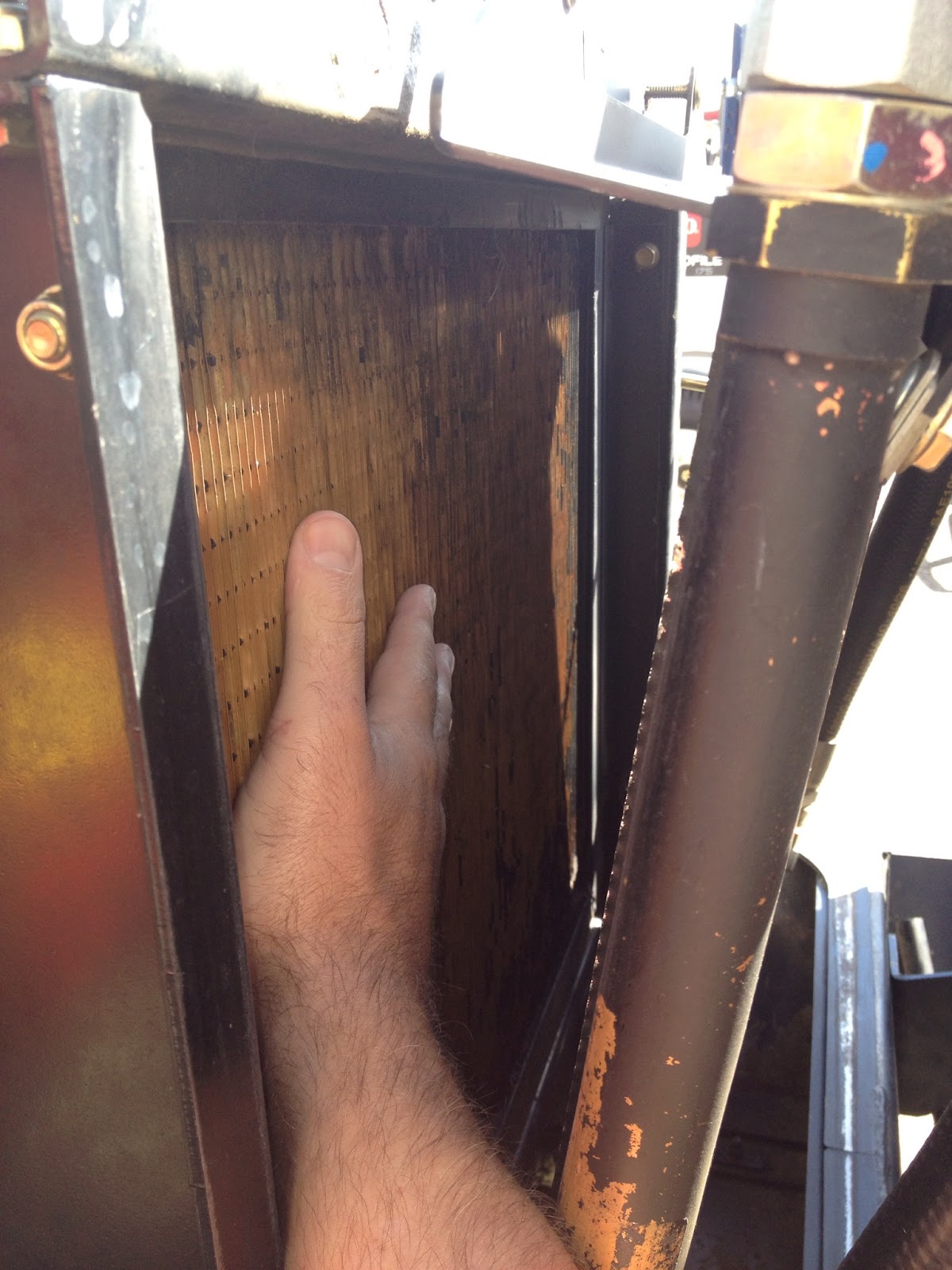
Without proper airflow over the radiator the is no chance the cooling system will operate properly. The easiest way to tell if you are getting airflow through the radiator is to check it with your hand. when I perform this test I open the hood, move the oil cooler out of the way and place my hand next to the radiator. *Do this when the machine is cold to insure the radiator is not to hot to touch! Move your hand around the radiator. Do you feel good flow through ALL areas of the radiator? Too often the corners or the bottom third are plugged solid. People blow out the center and feel they cleaned it, but they have missed portions. The other biggest problem I see is people using water to clean radiators. This will cause the bottom of the radiator to become completely plugged. It creates a concrete like surface that can not be blown out with air once it drys. We often have to completely remove the radiator to properly clean it at this point.
The fan clutch determines how fast the fan will spin. This is the aluminium piece that the fan is mounted to. There is fluid inside the clutch that stiffens up when the clutch warms up. So when the machine is cold there should be little resistance in the fan clutch. When warm, the fan should be harder to spin. If there is no change, the fan clutch is bad, and you are not spinning the fan fast enough.
If your fan clutch is bad (or you do not feel you are getting enough airflow) there is a Direct Drive fan clutch replacement kit. This kit was designed for machines with a cab & AC that put a heavier load on the engine. This kit is a aluminium block that removes the clutch and bolts the fan right to the pulley. There are some downsides to this approach though. The increased fan speed will increase machine noise. (Hearing protection is recommended) You may also need more frequent radiator cleanings and may influence the fan belt life.
Once you have determined what the root cause of your overheating problem is, another thing to watch for is how your hood seals against the radiator when it is closed. If there is not a proper seal, grass and other debris will plug the radiator much faster. Look at the weather stripping around the rear screen, does it make a good seal? If you have a 4500-D or a 4700-D the rear screen swings out of the way. Over time this screen can get bent and may need to be adjusted to get a proper seal.
Of course there can be other factors the come into play with an overheating concern, but from my experience these are the most common causes.
Jim
First off I should state that the electrical system on Toro equipment is designed to help identify an overheat situation. This helps us by either shutting the machine down, (or in more recently built machines) shut the PTO system off first, then if the temp continues to rise, shut the machine down. These systems are in place to save the engine from severe damage that can occur from an overheat situation. I caution people to never disable this function.
So what do you do if your machine is overheating? Virtually every time I see this issue it is related to one thing. Not enough airflow through the radiator. Either the fan is not spinning fast enough, or the radiator is plugged. This is how we diagnose this-
 |
| 1.Check the belt tension |
We test the belt tension with a 13mm wrench and put it on a fan mounting bolt. We then try to turn it clockwise. Can you turn the pulley with minimal force? If so, the belt is too loose causing the fan to not spin fast enough.
 |
| 2. Check the radiator for airflow blockage |
Without proper airflow over the radiator the is no chance the cooling system will operate properly. The easiest way to tell if you are getting airflow through the radiator is to check it with your hand. when I perform this test I open the hood, move the oil cooler out of the way and place my hand next to the radiator. *Do this when the machine is cold to insure the radiator is not to hot to touch! Move your hand around the radiator. Do you feel good flow through ALL areas of the radiator? Too often the corners or the bottom third are plugged solid. People blow out the center and feel they cleaned it, but they have missed portions. The other biggest problem I see is people using water to clean radiators. This will cause the bottom of the radiator to become completely plugged. It creates a concrete like surface that can not be blown out with air once it drys. We often have to completely remove the radiator to properly clean it at this point.
 |
| 3. Check the Fan Clutch |
The fan clutch determines how fast the fan will spin. This is the aluminium piece that the fan is mounted to. There is fluid inside the clutch that stiffens up when the clutch warms up. So when the machine is cold there should be little resistance in the fan clutch. When warm, the fan should be harder to spin. If there is no change, the fan clutch is bad, and you are not spinning the fan fast enough.
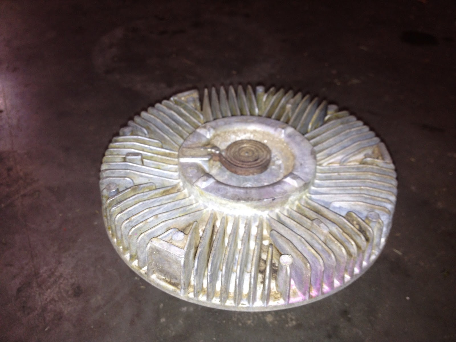 |
| *If the spring steel coil is missing from the front of the clutch, the clutch needs to be replaced |
3.1 The Direct Drive Kit (Toro #117-5665)
If your fan clutch is bad (or you do not feel you are getting enough airflow) there is a Direct Drive fan clutch replacement kit. This kit was designed for machines with a cab & AC that put a heavier load on the engine. This kit is a aluminium block that removes the clutch and bolts the fan right to the pulley. There are some downsides to this approach though. The increased fan speed will increase machine noise. (Hearing protection is recommended) You may also need more frequent radiator cleanings and may influence the fan belt life.
 |
Check the seal of the rear screen |
Of course there can be other factors the come into play with an overheating concern, but from my experience these are the most common causes.
Jim
Wednesday, September 12, 2012
What's that black box for?
That black box that has been collecting dust on your shelf is an ACE Diagnostic Display Tool (Toro Part# 85-4750). This (in my opinion) is the most underutilized tool in an Equipment Managers tool box.
 |
| ACE Tool |
The ACE Tool first made its appearance in 1989 with Toro's 580-D. Toro needed a way to troubleshoot the "brain" of the tractor. This tool allows us to test all of our input switches, the controller, the wiring, and the outputs, all in a matter of seconds without ever leaving the seat or pulling out an electrical schematic. Sound like it may be time to blow the dust off of it yet?
Lets take a scenario in which the tractor will not crank. The first thing I would do is find the loopback connector and plug in the ACE tool. Now I can test the most common of issues. Does the neutral switch work? Move the pedal and watch the light go on and off, yep the neutral switch works. Does the seat switch work? Sit down and check the light, yep that one works. Turn the key to crank, and no light? You have just narrowed the issue down to the key switch or the wiring to the controller.
 |
| Loopback Connector |
This is something that can be done in the field without any other special tools, or test equipment. Of course there are times where you will need a good multimeter and a schematic, but why jump to that if there is an easier way?
Those of you familiar with the tool may have noticed I have not mentioned the overlay that is used with the ACE tool. This is a plastic sheet that tells you what each light means when it goes off and on. It is specific to each model number. For the example above, I did not need the overlay. all I was checking was inputs. When we get a little deeper into troubleshooting, we will want to test what the controller is telling the machine to do and that is when knowing what each light means will help us.
*Do not let not having the correct overlay keep you from using the tool!
 |
| ACE Overlay |
The best advice I can give someone trying to use the ACE Tool for the first time, is just plug it in and try it. Once the lights come on, start flipping switches (inputs) and see what the tool does. You will get the hang of it very quickly. Press the toggle input-output button and find out what the controller is telling the machine to do. Do you having a flashing output light? there is a fault in that circuit, check that output.
Not all of Toro's machines have the ability to use the ACE Tool. Some of the machines that work with this are- 580-D, Reelmaster Fairway units, & Groundsmaster 4000 series units with switches to lift the decks.
*As a side note- If you have a leak detector on your fairway unit. You need to be using this tool when you fill your machines hydraulic tank to ensure it works properly.
Some of the other units use a Standard Control Module with built in diagnostic lights. I will cover this in an upcoming post.
Tuesday, September 11, 2012
Welcome to MTI Service
In my first post I would like to introduce myself and give
you an idea on what to expect going forward with this blog.
I am Jim King and I am the Service Manager at MTI Distributing in Brooklyn Center, MN. We
are the Toro Distributor for MN, ND, and Portions of WI, SD, IA, IL, & MO. I will be focusing on mainly Commercial Toro
Equipment and Service. Prior to coming
to MTI, I was an Assistant Superintendent / Mechanic at several courses in MN
and WI. While I love what I do here, I
often miss the turf side and appreciate when I get the opportunity to get back
outside.
Each post I will try to bring you helpful tips about your
Toro equipment, and try to give you things to look for based on the season. When I first started working on equipment I
felt there were too many secrets. The
people around me felt I had to “learn the hard way”. I never understood this; I want to share what
I know to help others in the industry. Along the way I will try to add pictures and
videos to help better explain the details of each post.
So welcome to the MTI Service Blog. I look forward to sharing more in the future.
Jim King
*The views in this Blog are my own and do not reflect the
views of MTI or Toro in any way.
Subscribe to:
Posts (Atom)